CellTrace™
Indoor Prediction Tool Based on Ray Tracing
 CellTrace™ is a suite of software tools that addresses Radio Frequency (RF) planning, design, modeling, analysis and optimization of wireless communication systems within buildings, tunnels, stadiums and in campus environments. CellTrace™ is a suite of software tools that addresses Radio Frequency (RF) planning, design, modeling, analysis and optimization of wireless communication systems within buildings, tunnels, stadiums and in campus environments.
It supports a wide variety of Air Interfaces, including but not limited to LTE, WiMAX (802.16x), Wi-Fi, CDMA, UMTS, GSM, and TETRA. It also supports MIMO technology, Distributed Antenna Systems (DAS), leaky feeder cables and a number of other transmissions modes.
CellTrace™ uses 3D vector databases with planar objects, each with their own individual properties, combined with extremely fast & accurate propagation models to compute path loss and wide-band properties, such as delay and angular spread, LOS/NLOS, directional channel, impulse response, angular profile, and propagation paths, of radio links within buildings.
Depending on the application, CellTrace™ offers static, Monte-Carlo, and dynamic network simulators. It also allows for the planning of coverage and capacity as well as network simulations.
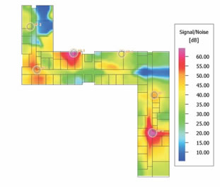 With regards to coverage, different transmission modes can be defined (bandwidth, MCS, data rate, SNIR target, signal threshold, Tx power,...) and the coverage maps (cell assignment, best server, active set, channel quality, Rx power in DL & UL, SNIR,...) are computed individually for each transmission mode. Link adaptation is considered and depends on the channel quality predicted with the propagation models. Maximum received power as well as maximum achievable data rates are predicted accurately for each location in the coverage area. With regards to coverage, different transmission modes can be defined (bandwidth, MCS, data rate, SNIR target, signal threshold, Tx power,...) and the coverage maps (cell assignment, best server, active set, channel quality, Rx power in DL & UL, SNIR,...) are computed individually for each transmission mode. Link adaptation is considered and depends on the channel quality predicted with the propagation models. Maximum received power as well as maximum achievable data rates are predicted accurately for each location in the coverage area.
CellTrace™ computes the capacity (throughput, max. data rates, packet delays, QoS, etc.) of the different radio links and cells in the network based on the coverage analysis and the traffic assumptions. Capacity limitations and overloaded cells can be detected easily and networks can be optimized to provide both high capacity and throughput.
Capacity improvements due to MIMO and/or Beamforming are modeled accurately because of the sophisticated, deterministic propagation models. Arbitrary antenna configurations (linear, circular,...) are possible and their impact on the radio channel - determined during the propagation analysis - is considered in the network planning.
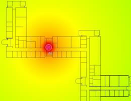
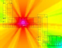
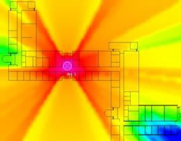
CellTrace™ has the most advanced RF propagation algorithms, based on 3D ray-tracing and prevalent path, that predict accurately indoor environments, tunnels, stadiums and any other location.
3D IRT (Ray Tracing)
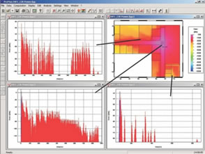 Ray optical propagation models suffer from long computation times. CellTrace’s unique 3D IRT with a single preprocessing of the building data reduces computation times for indoor databases with more than 1,000 objects, to less than a minute. This allows high accuracy and wide-band channel characterization (impulse response, delay spread, etc.) to be combined with fast computation times. Ray optical propagation models suffer from long computation times. CellTrace’s unique 3D IRT with a single preprocessing of the building data reduces computation times for indoor databases with more than 1,000 objects, to less than a minute. This allows high accuracy and wide-band channel characterization (impulse response, delay spread, etc.) to be combined with fast computation times.
IDP (Dominant Paths)
CellTrace’s Dominant Path Model is the best selection if:
- Fast and accurate path loss predictions are required
- Interference with outdoor TRX is important and outdoor coverage in urban or rural scenarios must be computed
- The database is only available in scanned maps
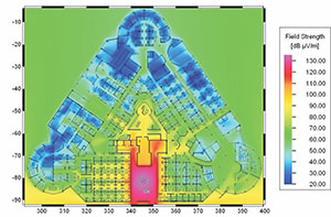
Multi Floor Predictions
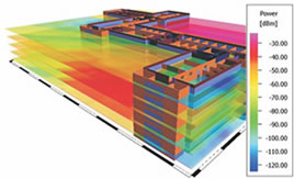 Multi floor buildings require predictions for each floor. CellTrace can compute predictions on an arbitrary number of heights and can display the results in 3D views. This allows for the easy analysis of interference between floors as well as coverage problems on floors without TRX. Multi floor buildings require predictions for each floor. CellTrace can compute predictions on an arbitrary number of heights and can display the results in 3D views. This allows for the easy analysis of interference between floors as well as coverage problems on floors without TRX.
Graphical Database Editor
The generation of the building databases was one of the biggest problems for the indoor propagation models for a long time. CelWall, an innovative CAD tool of the CellTrace suite, allows the generation of building databases within a few minutes based on either scanned bitmaps or CAD data (2D and 3D). The user can edit, modify, delete, rotate, move, scale, etc. the objects and define their properties (thickness, colors, materials, electrical properties, etc.)
CellTrace™ comes in two versions to address the specific needs of the end-user:
- CellTrace™ I: Supports the indoor deployments of all wireless technologies, including inside tunnels
- CellTrace™ D: Supports only Wi-Fi propagation and network documentation
The following ad-on modules are also available for CellTrace™:
- CellComp, which includes all components for indoor network planning.
- CellAntenna, which offers a convenient facility to generate and edit antenna patterns.
Downloads
 CellTrace Brochure CellTrace Brochure
|
|
| Product |
CellTrace I |
CellTrace D |
Description |
Databases |
| Indoor Walls: 3D Vector Data |
X |
X |
Arbitrary shaped and oriented planar 3D objects, including individual material |
Propagation Models |
| Empirical / One Slope Model |
X |
X |
Prediction of signal level (path loss, power, field strength) No obstacles between Transmitter (Tx) and Receiver (Rx) considered. |
Vertical / Direct Ray
COST 231 Multi Wall & Motley-Keenan |
X |
X |
Prediction of signal level (path loss, power, field strength) and LOS/NLOS
Obstacles in vertical plane between Tx and Rx considered (attenuation due to diffractions (topography, clutter, buildings) or penetrations (indoor walls). |
3D Single Path
3D Dominant Path Model (DPM) |
X |
X |
Prediction of signal level, propagation paths, and LOS/NLOS. |
3D Multiple Paths
3D Standard Ray Tracing (SRT)
3D Intelligent Ray Tracing (IRT) |
X |
X |
Prediction of signal level (path loss, power, field strength), delay and angular spread, delay and angular profile, propagation paths, and LOS/NLOS. |
Transmitter Types |
| Isotropic Radiator (without antenna pattern) |
X |
X |
|
| Directional Antenna (2x2D or 3D antenna pattern) |
X |
X |
Supported File formats for pattern: 3D CelTrace, 2x2D *.msi or ASCII |
| Leaky Feeder Cables |
X |
X |
Specification of coupling loss and attenuation of cable |
| Satellite Transmitters |
X |
X |
Either geostationary or moving satellites (broadcasting and navigation) |
Prediction Modes |
| Horizontal Prediction Plane(s) |
|
|
|
| Relative prediction height(s) |
X |
X |
Relative to ground |
| Multiple prediction heights (inside buildings) |
X |
X |
Only in Empirical/Direct Ray/DPM/SRT mode. Not supported in IRT mode. |
Arbitrary Prediction |
|
|
|
| Arbitrary oriented prediction planes |
X |
X |
Planed oriented arbitrarily in the scenario |
| Multiple prediction points |
X |
X |
Lists with multiple prediction points (individual and arbitrary heights) |
Database Converters |
| Pixel to Vector Data Converters |
X |
X |
Conversion of Bitmaps (*.bmp), JPEG (*.jpg), TIFF (*.tiff) to vector data |
| Vector: Indoor Vector Objects: CAD Set |
X |
X |
AutoCAD *.dwg, *.dxf |
Export of network/transmitter data and simulation results |
| Export of transmitter data and settings |
X |
X |
Supported file formats: ASCII Lines |
| Export of simulation results |
X |
X |
Supported file formats: ASCII Grid / DXF / Geo Bitmap (*.bmp. *.jpg, *.tiff) |
Software Tools |
| CelMan: Propagation and Network Planning Tool |
X |
X |
GUI to edit project parameters, visualize prediction results,…. |
| ACell: Antenna Editor (without CelAntenna) |
X |
X |
GUI to edit, convert, and visualize antenna patterns |
| CelWall: 3D CAD and GIS Editor |
X |
X |
GUI to work with 3D CAD and GIS data (Basic module) |
| CelWall: 3D CAD editor for planar objects |
X |
X |
GUI to work with 3D CAD data with planar objects |
| TuMan: 3D CAD editor for tunnels |
X |
N/A |
GUI to work with tunnel data (cross sections and trajectories) |
Air Interfaces |
| GSM / GPRS / EDGE (arbitrary TDMA air interfaces) |
X |
N/A |
Can be adapted by the user to any other TDMA air interface |
| UMTS-FDD (WCDMA) incl. HSPA |
X |
N/A |
A dynamic system simulator is additionally available |
| UMTS-TDD / TD-SCDMA |
X |
N/A |
|
| CDMA-200 incl. EV-DO |
X |
N/A |
|
| W-LAN IEEE 802.11 a/b/g/n (Wi-Fi) |
X |
X |
|
| WiMAX 802.16-2004 (Fixed) & 802.16e (Mobile) |
X |
N/A |
IEEE 802.16-2004 (Fixed WiMAX) and IEEE 802.16 e (Mobile WiMAX) |
| LTE |
X |
N/A |
|
| TETRA |
X |
N/A |
|
Extensions |
| MIMO Technology |
X |
X |
|
| Distributed Antenna Systems (DAS) |
X |
X |
Multiple antennas radiating the same signal => superposition, etc. |
| Leaky Feeder Cables |
X |
X |
Only if leaky feeder cables are supported in propagation scenario |
| Number of transmission modes |
Unlimited |
Unlimited |
Multiple transmission modes with individual parameters |
Simulator |
| Static Network Planning |
X |
X |
Interference due to cell load independent from traffic cells |
Consideration of Interference |
| Downlink: Cell Load (Relative Tx power |
X |
X |
Relative percentage of max. available power used for interference |
| Uplink: Noise Rise |
X |
X |
Can be specified for each cell individually |
| Definition of location specific interference |
X |
X |
Different linear polarizations of signals influence interference |
| Adjacent Channel Interference |
X |
X |
|
Simulation Modes |
| Simulation of horizontal grids on multiple heights |
X |
X |
One height (all scenarios) or multiple heights (only indoor scenarios) |
| CNP simulation (outdoor & multiple indoor heights) |
X |
X |
CNP urban/indoor simulations |
| Point to Multi-Point Mode |
X |
X |
Simulations for individual points |
Predicted Results |
| Cell Assignment and Consideration of downlink transmission |
| Best server / Cell layout |
X |
X |
Results are depending on selected algorithm for cell assignment |
Neighbor cell list |
X |
X |
Neighbor cell list (based on cell assignment) |
| Max. received power |
X |
X |
Max. received power in downlink (e.g. used for cell assignment) |
| Number received carriers / sites |
X |
X |
Number of received carriers / sites /cells in cell assignment |
| Soft / Softer handover regions |
X |
X |
Type of handover (hard, soft, softer) incl. size of active set |
| Downlink & Uplink transmission modes |
| Min. required Tx power |
X |
X |
Min. required MS and BS Tx power required for transmission mode |
| Max. received Rx power |
X |
X |
Max. received MS and BS Rx power required for transmission mode |
| SNIR (Downlink) |
X |
X |
Max. available SNIR for transmission mode (in downlink) |
| Reception probability (DL) |
X |
X |
Percentage for coverage incl. fast fading (Rayleigh fading) |
| For all transmission modes |
| Number of MIMI Streams (DL, UL) |
X |
X |
Number of carriers influences number of radio links. No carrier assignment |
| Throughput / Bit Rates (DL, UL) |
X |
X |
Highest achievable bit rates available for pixel (downlink, uplink) |
Definition of Mobile Stations (MS) / user Equipment (UE) / Subscriber Stations |
| MS properties for each transmission mode |
Individual |
Individual |
Same or individual MS properties for each transmission mode |
Definition of Base Stations (BS) / Access Points / Satellites / Cells |
| Number of carriers to be assigned to a cell |
1 |
Unlimited |
Number of carrier influences number of radio links. No carrier assignment |
| Noise figure / Cable losses / etc. |
X |
X |
Default for all BS in network or individual for each BS |
|